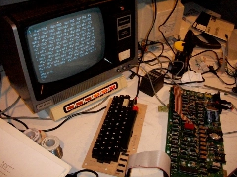
This is the story of bringing up and repairing a TRS-80 that had not been powered on in 30 years.
Around the summer of 2013 I bought a number of old computers from a retired professor in NJ. My main interest was a TRS-80 model I level II system.
So I finally got around to checking it out in spring of 2014. I unboxed it and found it very complete with cables, cover panels (often lost), software and manuals. I muddled through the unfamiliar system setup and noted that the vintage documentation didn’t disclose the orientation of the drive cable connectors very well.
I powered it on and found that it was pretty much stone cold dead. Though I have no doubt that it was working when stored it didn’t work now. There was no video output at all on the monitor. I think the power light on the keyboard unit was on. That’s all. Now I had been through a repair of a broken Model I 4K Level I console earlier this year, so I had some confidence. I promptly got to work.
Problem #1, Power Supply
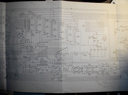
An essential guide for working on TRS-80 computers is the TRS-80 MODEL I Technical Reference Manual. It is widely available in PDF format, but I have two printed copies. The manual has very detailed discussions of the theory of operation of all the sections of the Model I, fairly complete trouble shooting guides, and full schematics. It may be the very best technical manual provided with any of consumer microcomputer. Its a lesson in electronics and vintage computer architecture.
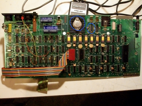
Following the power supply trouble shooting section, I found that the 5V supply was dead. Regulator Z1 was observed to be overheating indicated by scorched skin on my index finger. It seemed to me it was a failure of regulator IC Z1 or power transistor Q4 which are circled in this photo of the system board contained in the keyboard.
(Note: Q4 is mislabeled Q2 in manual) I ordered replacements for both and installed them. First I replaced the regulator Z1, that didn’t fix it. Then I replaced the 5V transistor and the 5V sprang to life. Probably just Q4 was at fault. At the same time, I also replaced all the electrolytic capacitors because, as us vintage computer guys know, these capacitors tend to fail from age. With the 5v fixed, the unit showed a little bit of life.
In hindsight, the failure of the power supply probably happened when I turned it on, and probably caused the further failures detailed below- the damage of CMOS ICs.
Video Sync Problem, Problem #2
I now had some video activity on the monitor but it was very messed up. I unfortunately didn’t take a picture of this. The display was “tearing up” -like a poorly tuned TV station. I could barely perceive some character dots mixed in the noise. That was encouraging. This was looking like a video signal timing issue. My bet was the computer was at fault, not the monitor. This was proved out by quickly trying a second monitor, which showed the same symptom. Pulling from experience with video test equipment I looked at the video signal on my scope and concluded that the computer was not forming the video signal correctly. The waveform simply looked nothing like a black and white video signal. Conspicuously missing were the horizontal and vertical sync pulses.

The tech reference manual covers the video generation in great detail and pointed me to the parts of the schematic that make the video signalling. In short, a part of the circuit makes vertical pulses (which signal return the beam to the top of the screen), another part makes horizontal line pulses (which return the beam to the left of the screen after every trace across), and another decodes the screen data into the dots that go across the screen, All of this should get mixed together in another part. My thinking was the pulses either weren’t getting made or they weren’t getting mixed properly.
The video generation section of the TRS-80 “free runs” off of the main system clock and constantly displays whatever is in the video memory. It needs no help from the Z80; it doesn’t matter if the the Z80 is running at all. But if the processor is not running the data in the video memory is never initialized, so its content is random data. Many ailing TRS-80s end up with this symptom- a nice clear video picture of random characters- when something is preventing the Z80 from running.
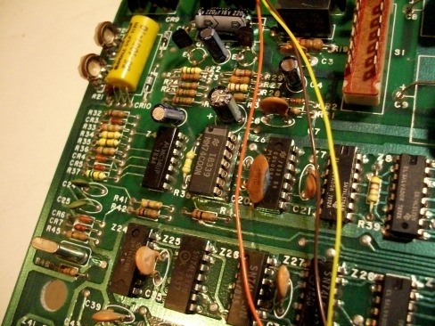
But this wasn’t the case with mine. The video generation was so messed up it would not control the monitor properly. The manual suggested places to scope to follow the progress of all the sync construction and mixing. Poking around the sync generation chips I found there were properly timed horizontal and vertical pulses happening up until pin 3 of Z5 (circled), the mixing point of the signals. Here at pin 3 the logic signals were not swinging “rail to rail” (0 – 5v) like a logic signal should. To me this indicated that that IC had failed, This IC was one of the several CMOS type ICs which the manual warns are likely points of failure due to their fragile semiconductor construction.
I ordered a replacement and weeks later I installed the new part. It worked. Horizontal and vertical pulses were proper now, and the video snapped into clarity. Problem #2 down. This photo is the replaced IC, a 74C00 NAND gate, sitting in an installed socket smack in the middle to the left of the orange wire.
What The… Problem #3
Here’s what the nice crisp display presented to me:
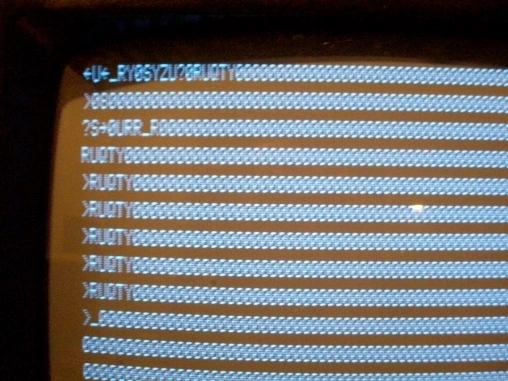
Yikes. Its supposed to just say “READY >” READY looks like RUQTY and what are all those zeros! But how “wrong” is this really? It looks horribly wrong but its actually really close to correct.
Some of the characters are right, some are wrong. The big clue is that the zeros should be spaces. The key is that the ASCII code for zero is only one bit different from the ASCII code of a space- a zero has bit 4 set where as a space has bit 4 clear. Looking at the rest of the wrong characters, you can see that they have the same flaw, bit 4 is set where it should be clear. The conclusion is bit 4 is stuck set to 1 in the display memory. If bit 4 is stuck on , an E turns into a U, A into Q, and space into 0. Characters that are supposed to have bit 4 set to 1 are not affected such as R and Y. This is why spaces are zeros and “READY” reads “RUQTY”.
If there is a bit stuck in memory, you might ask, how can the processor run at all? That’s because the video memory is separate memory from the CPU’s instruction and data memory. Its function is to only contain character codes for each position on the screen. Each bit of a character code comes out of its own 1-bit wide “2012” memory IC. There are 6 memory ICs holding the bits of each of character.
6 ICs? 6 Bits? Yes 6. Radio Shack made the design decision to only use 6 bits permitting representation of only 64 character codes. That’s only enough for upper case codes. Another IC to hold a 7th bit- which would have allowed lower case characters- was sacrificed to save $1 of build cost. But if you think about it, the competition was effectively the Apple II and PET, which were also upper case only. Precedent set, an extra chip would be a hard sell to management at Radio Shack I suppose.
Z61 Replaced
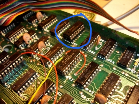
After yet another ebay purchase cycle, I replaced Z61 show circled:
As an aside, note the curiously stacked chips in the middle of the above photo with the orange and yellow wires. This modification was done by the original owner to add a 7th memory IC to hold a 7th character code bit. Special software and keyboard support could then be used to produce lower case characters.
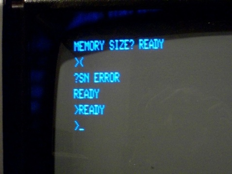
Characters displaying correctly now.
But what’s with the “?SN Error”? Well I’m working with a disassembled system on the bench- the keyboard is not attached. It turns out, this makes the system software malfunction. It erroneously thinks keys are pressed. It happens randomly.
Why? Well the keyboard assembly has “pull ups” (resisters tied to +5) on the data lines. When keys are pressed their corresponding data lines are grounded, making the lines a read logical ‘0’. Keys not pressed therefore read as a ‘1’. Without the keyboard attached, the data lines are missing these pull-up resisters. This condition is called a “floating”. The lines are neither high or low, and in fact they act like little antennas picking up stray electrical interference and can read a ‘0’ or a ‘1’ unpredictably. So without the keyboard assembly attached, all bets are off about what the system thinks is going on with the keyboard. This nonsense will stop when the keyboard is attached. It is important when trouble shooting that you know which behaviors are really a problem and which ones aren’t, or you will waste a lot of time troubleshooting non issues. In this case, the ramifications of running the system partially disassembled are important to understand.
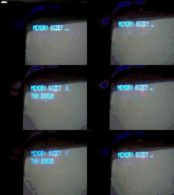
Random key reads in action:
On the bench it might carry on like this until Reset was pressed. Apparently that changed the electrical conditions just enough to make it settle down.
Double Characters? Oh no.
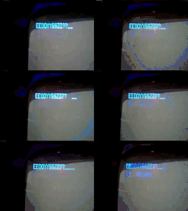
Then all of a sudden I started getting this.
This had me going in circles for a while. About 1.5 minutes after power up the display would switch from normal to text to this double character nonsense. It was harder to blame this on the floating keyboard lines. This data change suggested another video memory issue. It seemed to happen after a bit of snow flickered through the display. Sometimes a reset would fix the display sometimes it wouldn’t. So I thought it was a thermal issue, but cold spray didn’t prove that. No response anywhere. I re-seated the RAMs and the processor. That may have improved it but not fixed it. I changed processors to see if the processor was flaking out… unlikely really, but grasping at straws here. No difference.
Now this computer contained another mod: a small board called the XRX that was created to improve the quality of the cassette signaling. Twice when I touched it I observed the display correct itself. So I suspected a cold solder joint I touch up the pads on the that board. It seems to have done the job. But I didn’t think that this little board was hooking into anything that sensitive so I’m not sure if that fixed it or something else. After full assembly and many hours of use this behavior never returned.
New cable for the keyboard, Problem #4
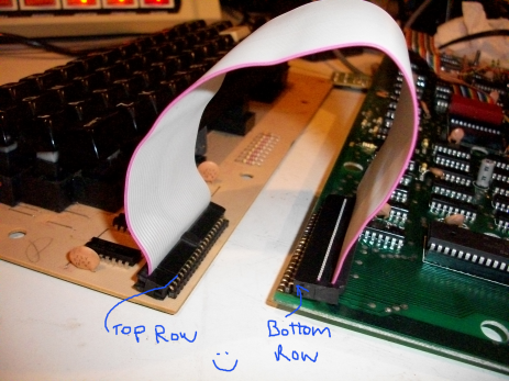
The TRS-80 internal ribbon cables would fail from age. The construction has strips of foil sandwiched between two layers of plastic. The layers eventually de-laminate, and the foil traces move and short together. A good practice is to replace them with a IDC cable. First, you remove the old cable from the boards. I prefer to cut all the pins near the board and extract each pin individually. Then you install 20 pin single-row right-angle edge male IDC connectors onto the boards. For the cable you can re-purpose a PC IDE cable. I cut off the longer section (motherboard end) leaving the two connectors from the IDE drive end. Because of the way the cable flips over, you plug the top end of the cable onto one side and the bottom row into the other side (as shown in the photo) in order to have continuity from one side to the other.
Oops. I broke it.
After constructing this, I tested it and guess what I got. Random characters on the screen- a stuck Z80! Somehow my cable was preventing the processor from running. Why? Well it turns out the processors actual data bus travels on this cable. If you mess up the signaling on the cable, the processor can;t access its instructions and data. Under very close examination I found solder bridges on several header pins on the keyboard side.
After fixing those, the processor ran properly again. Now I could test the key presses. I ran through the keys and found some didn’t work.
Again.
I cringed that it might be bad keys; pulling keys is a pain. The keys were B J R Z 2 and ; It turns out these are all related- they are all on the same “scan line”. What this means is that one line on the cable selects these keys and if any are pressed, a respective bit on the data bus indicates which one. This suggests that the select pin on the cabling is not connected. Flexing the cable at the main board side showed an unreliable connection. Examining my soldering, it seemed I had very little flow topside of the new headers, The through-hole plating is not so good on these old boards so if you don’t get a healthy amount of solder from top side to bottom side, traces on one side may not connect through the hole to the other side. So I flowed a nice amount of solder top side and re-flowed the bottom pads too. That did the trick. No intermittent connections and the keys all worked now. The lesson is- as shorts on this cable assemble will crash the processor, opens will make the keys not work at all.
By the way- it was typical of the era to bring the processors bus across a cable for purposes such as this keyboard scanning. But not a good idea it puts the processors reliability at risk and the long wires with high frequency signals creates radiated interference. In fact the Model I had to be put out of production for FCC emissions problems, which the Model III fixed.
So now for the the vintage computer functionality test:
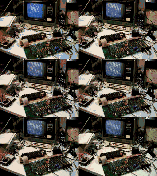
10 PRINT “HELLO WORLD “;
20 GOTO 10
It works!

The BASIC print command on early Microsoft BASIC interpreters handles line wrapping with interesting results. With specific text formatting, in this case by following HELLO WORLD with two or three spaces and a “;” the lines wrap in such a manner that the text appears to side-scroll. Apple ][s, Commodores, and TRS-80s all do this. By the time the IBM PC came out, Microsoft changed the behavior preventing the scroll. When a print didn’t completely fit at the end of the line, it begins the print on the next line.
The working setup
Its a thrill to step back and see the old thing doing what it was built to do once more.
Preparing for reassembly
I had to decide whether to keep the XRX board or remove it. I wondered if it was a liability. The conclusion was to keep it in order to preserve the historical configuration of the period user. It may be technically proper too. A ROM version was released that improved the cassette signaling making the XRX board unnecessary, but I don’ t think this unit has those ROMs. Further, I was also told I’d have to repair traces that were cut when the board was installed. So I freshened the double sided tape adhering the board to the keyboard and checked that all the wires were solidly connected. Npte the IDE cable folded in the lower left.
Fail. I broke it AGAIN!
I put the case back together and fired it up. I had no vertical lock. The text rolled continuously. Argh!
I pulled the whole thing back apart and knew were to look for this problem based on debugging the sync pulses first fixed- around Z5. Tracing the vertical sync pulse logic, I found a signal leaving from and IC output properly but arriving at its destination. In between, I found that one leg of a capacitor that the signal went through was broken off. A lucky find. This seemed to be a reworked item from the modifications done that turned the unit from a Level I to a Level II. I don’t know whether the “factory” did this mod or the original owner. The leads were long and had insulators installed over the long leads, and it was laid over on its side. I shortened up the leads and bent them to lay flat across the pads. Nice and solid. That fixed the problem and I reassembled the system unit for good.
Moving onto the Expansion Interface.
Problem #5 Won’t Boot from the drives
I did an initial hookup of the expansion unit. This was the first time I ever worked with one. After a quick review of the PDF manuals for the EI and the drives, I ‘deoxed’ (cleaned) the cables and connectors and hooked up the console and drives. And turned it all on. The drives spun up. But the console booted right to Basic. It didn’t attempt to actually go to the drives. On subsequent resets, it seemed to sometimes want to hit the drives . Something wasn’t right. By rights I should have checked out the drives before powering up. So I did it next.
Drives
I took apart the drives and they looked good inside, rails were clean and smooth. The spindles and head assemblies moved freely. I judged them ready for use.
Checking the EI board out.

First order of business is to check the power supply. Probably should have done that before hooking anything up. My board is an early design and it didn’t exactly match the Expansion Interface Tech Reference schematic. It was close enough though, that I found the 12v and 5v and those checked out fine. So I put it back together and figured I could get some debug going in Basic.
Power LED hack
Before going any further I had to deal with a frustration. The manual for the EI specifies specific order of power up of the EI, the system unit, and the drives. I don’ t know if in practice folks strictly paid attention to this. So my frustration in trying to obey the order was knowing whether the EI was turned on… no power light??? Come on! That will not do! So I hacked in an LED and mounted it in the expansion bay wall so that it could be seen through the air slots of the case. No exterior mods that way. Here is the LED leads picking up the 5v rails with the obligatory 330ohm resistor.
LED location

Functional yes but maybe not the smartest thing. If I get an RS-232 board I’ll have to probably need a different cable arrangement, where I’ll probably need to drill a hole for it to get it out of the way of the expansion slot. OK, it was quick and dirty but it works.
The LED
The light peeks through the cooling slots. Very happy that I can now see that the power is on or off.
Now wanted to know if the memory in the EI was being recognized. So I put the case back on and reconnected it to the console. Basic PEEK and POKE operations can be used to probe the memory and disk hardware. I read that Basic scans for the top of memory and its result could be read by the command: “print peek(16561) + peek(16562)*256” With the system unit alone the result should be 32K and with the EI it should read 64K. With the EI I got 64K! Good so far, the EI memory is being recognized. So the EI cabling and memory are functional.
With some experience I found that you can tell if the memory is being recognized without checking this value. Without the EI (or not recognized) the unit boots to Basic in about 1 second, and with the EI it takes ~3 seconds. The difference being the time to scan the 32k memory in the EI.
Testing the disk controller board
A knowledgeable person on the TRS-80 Yahoo board provided information regarding how to interrogate the disk controller registers. Drive Select Register: Status Register SR: 37E0h = 14304 decimal. Setting values 1,2,4,8 selects drive 0,1,2,3. On any select of a drive, all drive motors should spin up and the LED of the drive given in the select should light for about 3 seconds then go out. Status Register CR: 37ECh = 14316 decimal. I didn’t determine what the values should be. Sector and Track Registers: 37EDh and 37EEh These should r/w like memory. “Poking” the Drive Select register behaved exactly right. All reads however, from any of the registers, came back 0. Apparently the board/IC could be written but not read. Hoping it was a connector issue, I tore the EI apart again.
The controller board installed in the above photo is a Percom Doubler. It provides double density disk access in place of the single density controller IC. It sits in the IC socket and has no other support. This is a liability for poor connections. In my case it didn’t seem that well seated in the socket. So I removed it and cleaned the socket and pins and firmly replaced the board. I promptly reassembled the IE case and voila, I powered on the unit and held my breath as the screen full of random characters presented itself (normal at startup) and then BANG it booted to DOSPLUS! Sweet! The system’s first boot in probably 30 years.
Closeup – 8/8/79!
Built the summer after my high school graduation.

That’s it! A repair that dragged on over a few months, but is done. A few keys should be replaced to make the system nicer to work with. That’s for another day.



Thanks so much for the TRS-80 article. It gave me the courage to tackle two Model 1 that were not working. They are now fixed ! Especially liked the idea of the IDE ribbon cable to connect the keyboard.
LikeLike
Great news! Glad it helped you and your two Model 1’s.
LikeLike
Hi, Douglas. This is a great article. I bought a TRS-80 Model 1 and got a bit over exuberant and brought the motherboard (with the keyboard attached of course) to my daughter’s science class (I was doing a guest lecture on circuitry).
I later noticed that the 0,1,2,3,4,5,6,7 keys no longer works, and with a bit of experimentation, I found that the hole for pin 10 was not contacting. I tried melting the solder above it in hopes it would resettle but it didn’t help. Meanwhile I made the situation worse by causing a short somewhere on the laminated ribbon (just as you described.)
So, I’d like to replace the whole connection as you have done. Problem is, I’m not able to locate the IDE 1×20 right angle connectors as you have pictured. Could you point me to a place where I can purchase all the parts you have used?
Plus, are there any tips you can lend on soldering those pins causing neighboring solders to contact?
Thank you!
Brian
LikeLike
I’ll see if I can either locate some spare 1x20s here or get you a link to where I got them.
The technique to clean up the pins would show well in a video but I’ll try to describe. De-solder braid and flux is the key. Brush a coat of flux on and around the pins. Lay down the de-solder braid across the pins at one end and press the iron against the braid. After 5-10 seconds the braid will start to wick up the extra solder. Slowly slide the iron across the rest of the pins dragging the de-solder braid with it. At the right speed, the solder on the newly contacted pins will also melt and wick up the braid. What is left behind on the pins is usually a perfect amount of solder, with no bridges. I hope that makes it clear for you and works.
LikeLike
Brian – I purchased some through Ebay. (Very cheap from China if you don’t mind waiting 4 weeks !)
Just search for 40 pin right angle header. The 40 pin strips can easily be snapped into two (they are designed to break).
LikeLike
Thanks both. I’ll be moving forward with your advice. It’s stop-and-go, so don’t be checking back frequently!
LikeLike
Fabulous, well detailed and concise article, I just picked up a model 1 off of Craigslist and intend to reference this article in my attempts to bring it back to life.
Kindest Regards
LikeLike
Thank you Antonio. I know one other person that was aided by
it. If you are not already there,
the TRS-80 forum on VCFed.org is very active and has lots of
kind members there that are very knowledgeable and helpful.
The group help me get to the bottom of a Model 4D display issue and
even gifted me some parts. Good luck with the restoration!
LikeLike
Thank you so much Douglas, I am quickly becoming aware of how ill prepared I am to tackle this project, being aware however of the historical significance of this particular Machine I would like to have it looked at by someone with the knowledge and skills to properly bring it back to life, if you or any of your readers are interested Please contact me at 780tech@gmail.com.
Thank you again
LikeLike
Consider taking it one step at a time. It may not need near the work that mine did. I think the power supply failure took out a lot of it. Depending on what you know now, you could consider this an opportunity to learn a lot. The TRS-80 tech manual is a pretty good introduction to digital and computer electronics.
LikeLike
That keyboard is very odd… The red key is completely non-standard, and the normal Model 1 keyboard has a metal frame supporting the keys, not just a PCB. Any idea where it came from?
LikeLike
Hello: Yes. I should have elaborated about that in the blog. I think I highlighted about the ICs added for the lower case mod. This red key was added by the person who did the lower case mod, for which a key was added that worked with the common software modifications of the day. I have not tried it, but perhaps it was used as talked about here: http://www.trs-80.org/electric-pencil-lowercase-modification/
LikeLike
Cool… That said, you do have a pretty rare/old version of the Model 1 there since I’ve never seen that style of keyboard before. Most of them look like this: https://upload.wikimedia.org/wikipedia/commons/b/b9/Radio_Shack_Tandy_TRS-80_Model_I_Keyboard.JPG
ALPS even made a variant that had blank holes where the keypad goes for the 4k Level 1 machines of the day, so yours pre-dates even those.
In any case, a photo of the undersid of this keyboard would be a neat feature to add to some of the TRS-80 archives.
LikeLike
Buba Jones:
Right you are! I had not handled many Model I’s to notice that the keyboard (circuit board) was unique. The original owner of this computer was an early adopter, Serial number is low, but not remarkably low, at 26,652. I’ll see about getting a photo of the underside. The system is packed away right now.
LikeLike
Im glad Im not the only one that fixed and broke and fixed and broke and fixed and broke and improved and broke and fixed my TRS-80 before I could play with it.
LikeLike
Dave,
Do you repair TRS-80’s.
Brian
LikeLike
Hi- I might entertain that sometime, but for now I’m backed up with a basement full of prospective restorations…
LikeLike
Hi Brian , I have the same answer as Douglas. Too many jobs at the moment. Also it sometimes can take several hours to repair a TRS-80 so not really economical to repair at $50 / hr.
Dave.
LikeLike
My original Model I from 1979 is no longer working. It took a fall when I moved from NJ from PA. It would be worth it to me to get it working again. As a warning it has the Electric Pencil Mod, and the Dennis Kitsz High Speed Mod from the Blue Book. My E/I has also been modified to remove the DDU unit and to generate the memory timing signals directly from the Keyboard unit to enable the memory to work at the higher speed.
LikeLike
Hi Al- we have crossed paths at VCFEast (MARCH) over the years. Nice to hear from you, however, very sad about the Model 1. However based on what I went through on this fix, your issues should most certainly be fixable. Sounds like a good item to get a group working on at a workshop at Camp Evans.
LikeLike
Did you get it going?
LikeLike